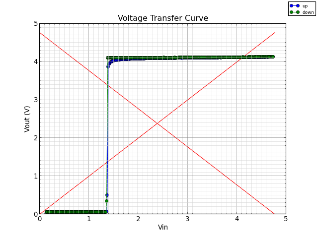
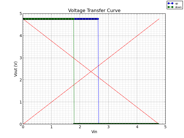
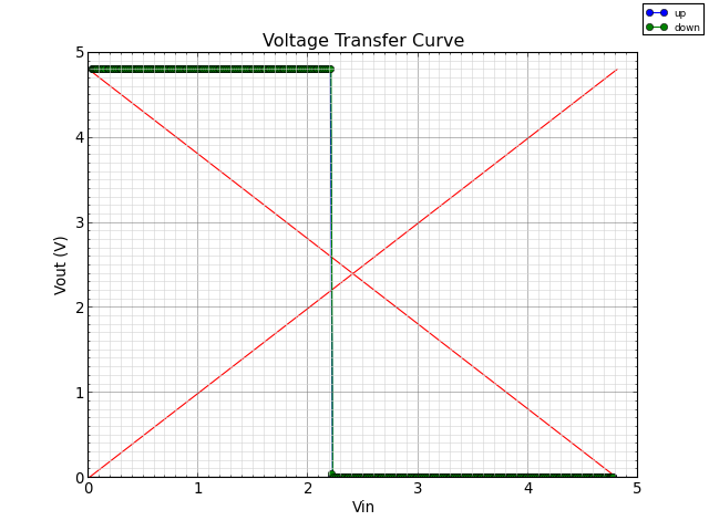
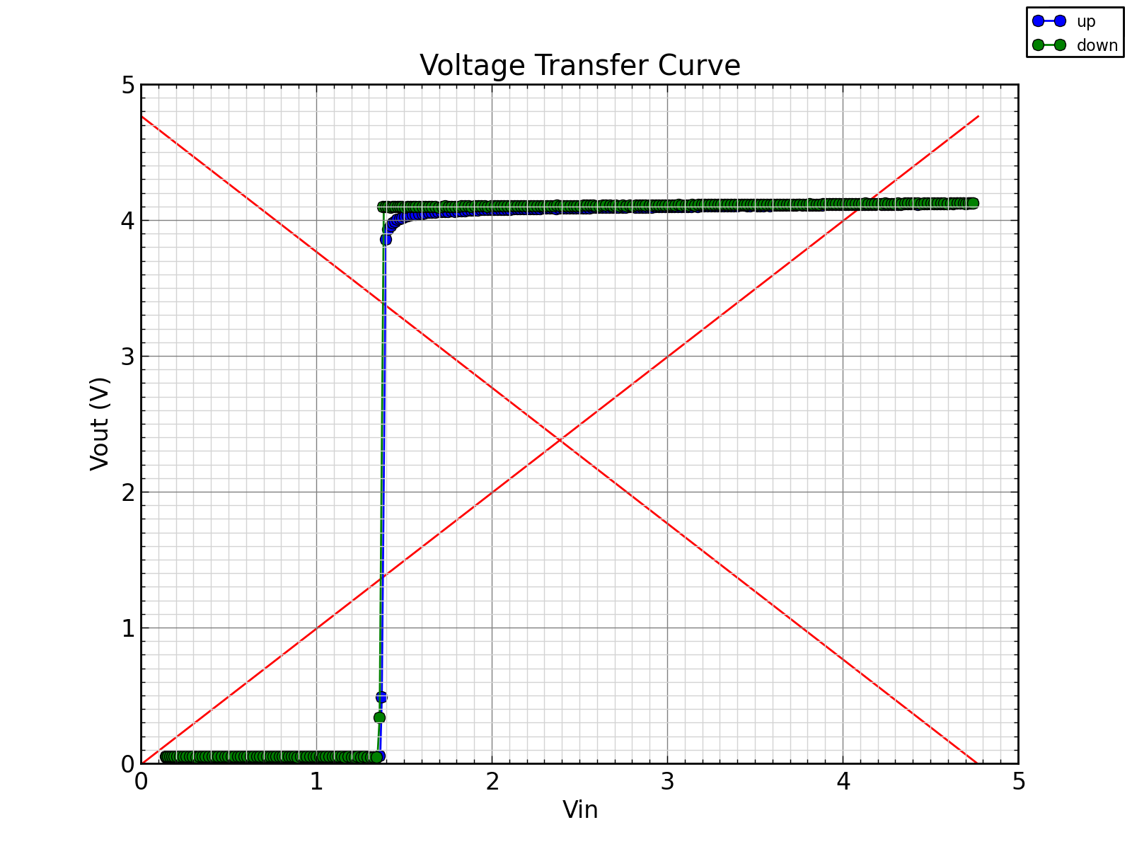
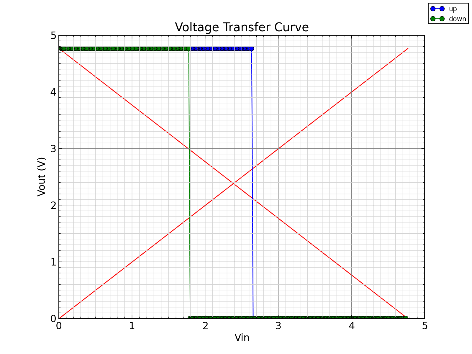
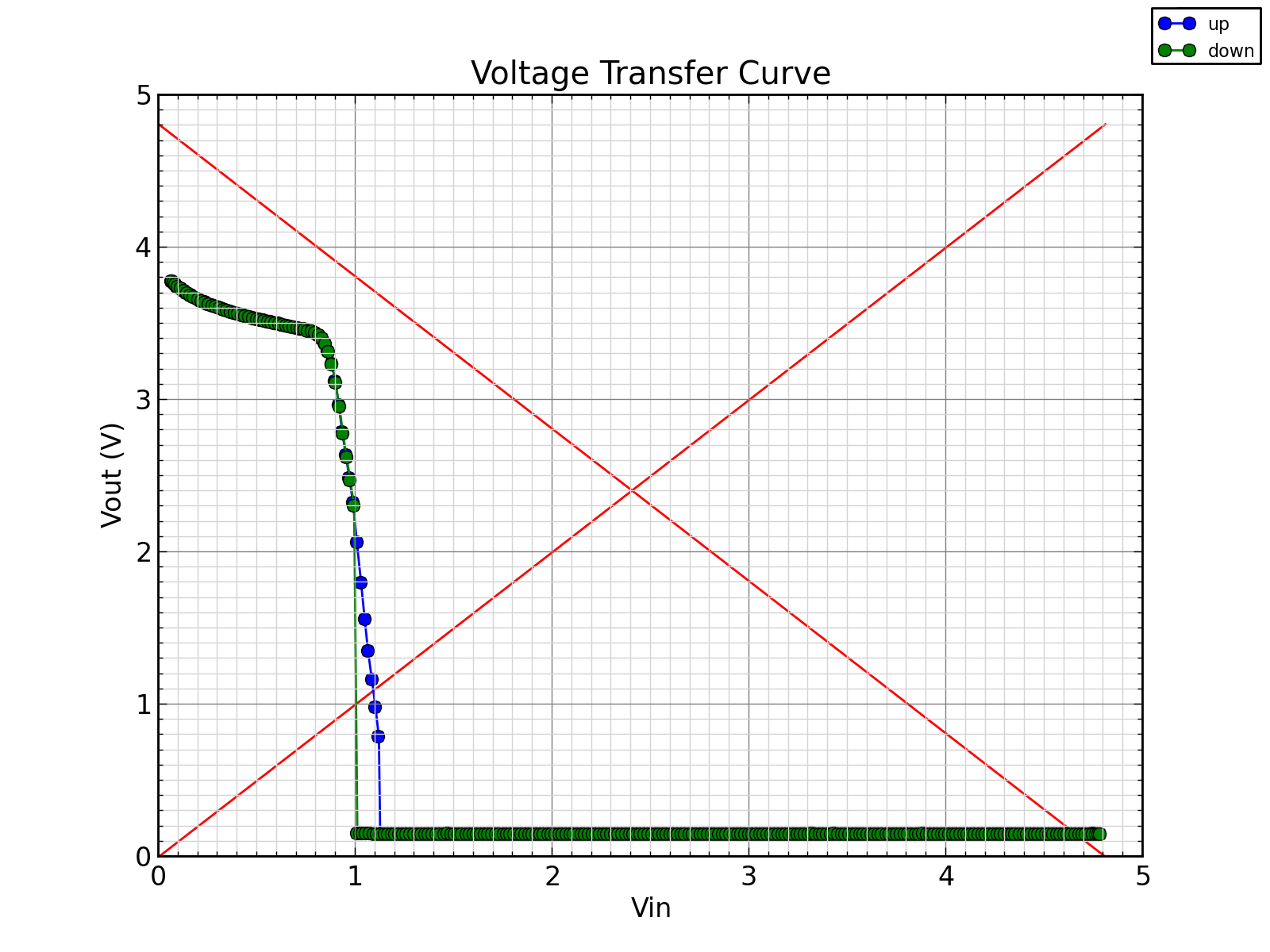
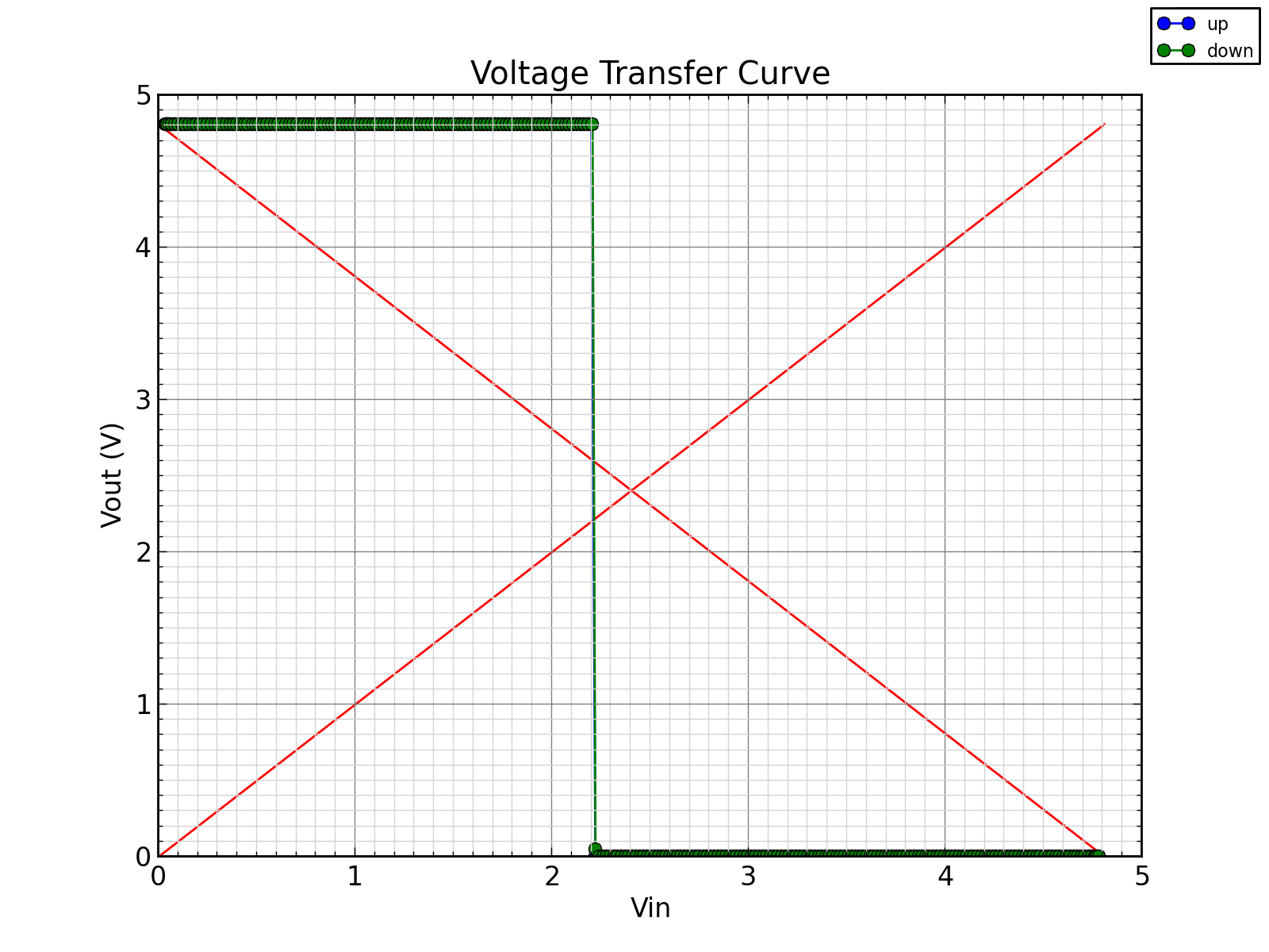
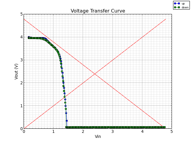
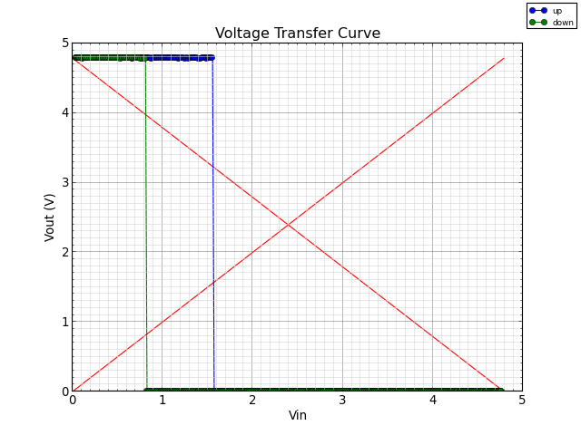
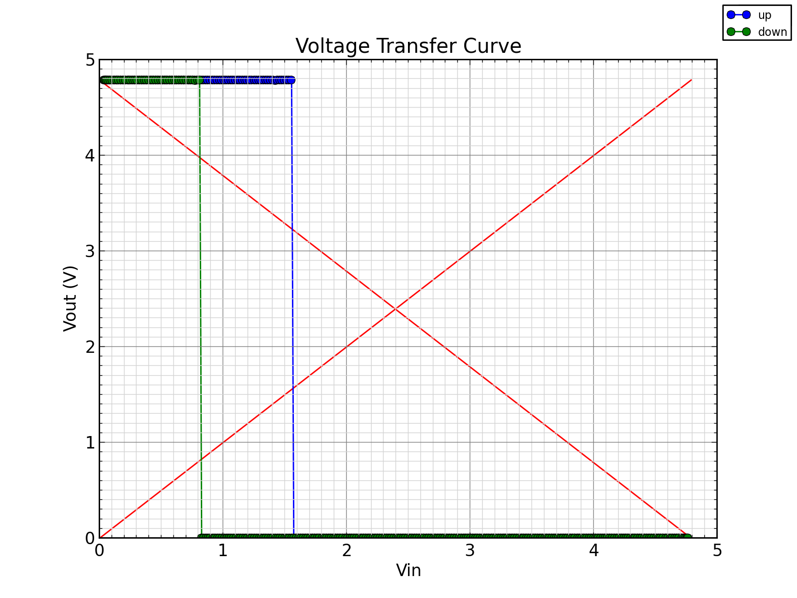
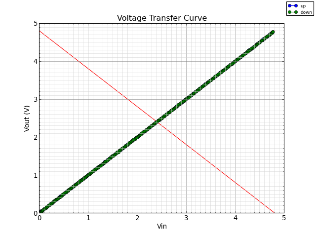
Voltage Transfer Curve
http://en.wikipedia.org/wiki/Inverter_%28logic_gate%29#Performance_measurement
Schematic:
.-----------------------------------------------------------------.
|                         Arduino                                 |
|                                    pin_x_in=A2                  |
|                                                                 |
|                         pin_amp_out=A1   |                      |
|  pin_pwm=D9                              |    pin_x_out=A3      |
|                              |           |         |            |
'-----------------------------------------------------------------'
       |  100k        MC33201  |Vamp       |Vin      |Vout
       |  ___            |\    |           |         |
       '-|___|--o--------|+\   |     ___   |  .---.  |
                |        |  >--o----|___|--o--| X |--o
               ---      -|-/   |           |  '---'  |
          100n ---     | |/    |   R=120  ---       ---
                |      |       |          --- 100n  --- 100n
                       |       |           |         |
               GND     '-------'          GND       GND


