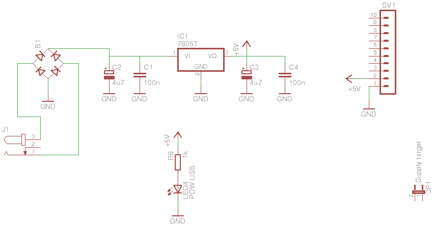
9. External power
Status: under construction
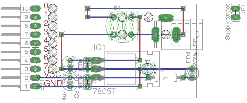
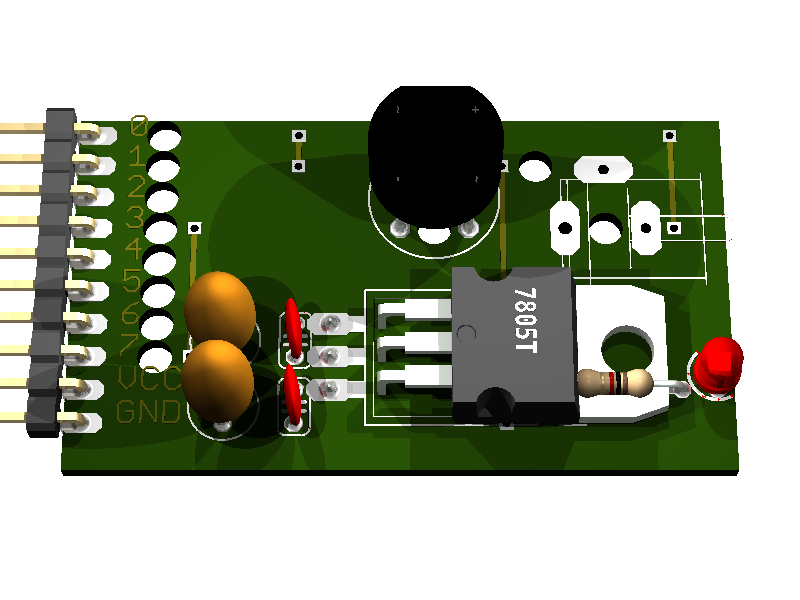
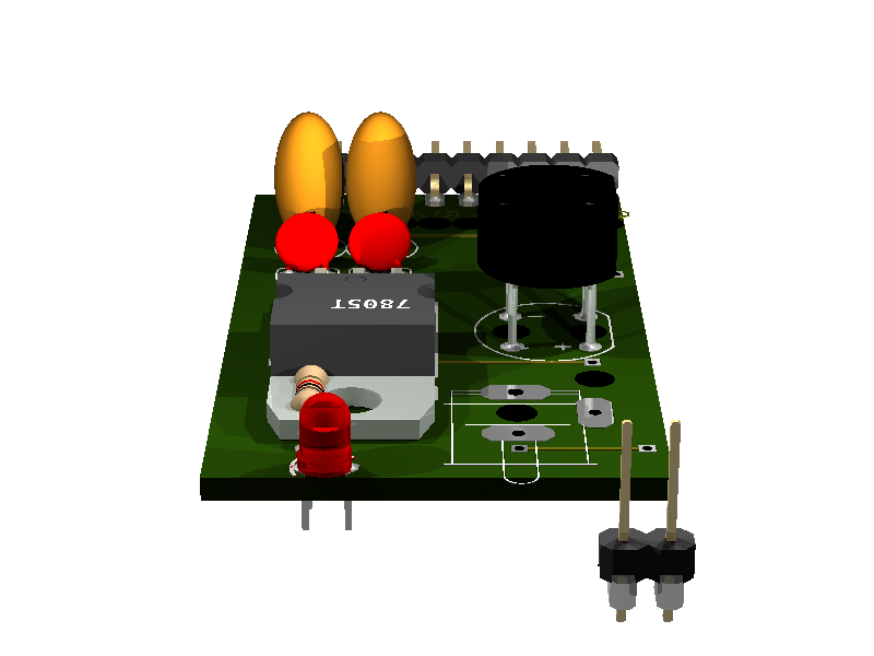
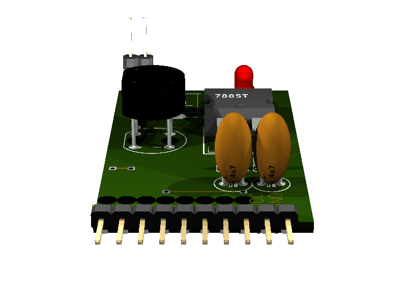
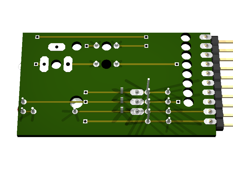
9.2. Board
top view:
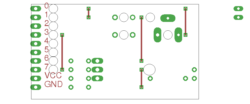
wires only:
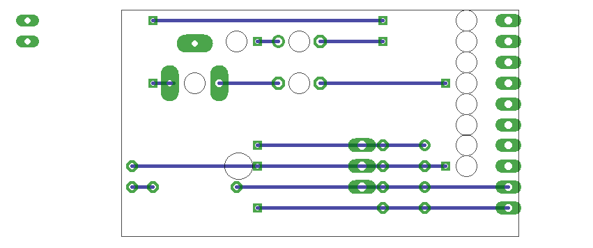
bottom view mirrored:
9.3. Partlist
| part |
value |
position |
|---|
| B1 |
|
(1.5 0.9) |
| C1 |
100n |
(1.1 0.45) |
| C2 |
4u7 |
(0.9 0.45) |
| C3 |
4u7 |
(0.9 0.25) |
| C4 |
100n |
(1.1 0.25) |
| IC1 |
7805T |
(1.6 0.4) |
| J1 |
|
(2 0.8) |
| JP1 |
Supply target |
(2.8 1.05) |
| LED4 |
POW USB |
(2.3 0.35) |
| R8 |
1k |
(2 0.3) |
| SV1 |
|
(0.5 0.65) |