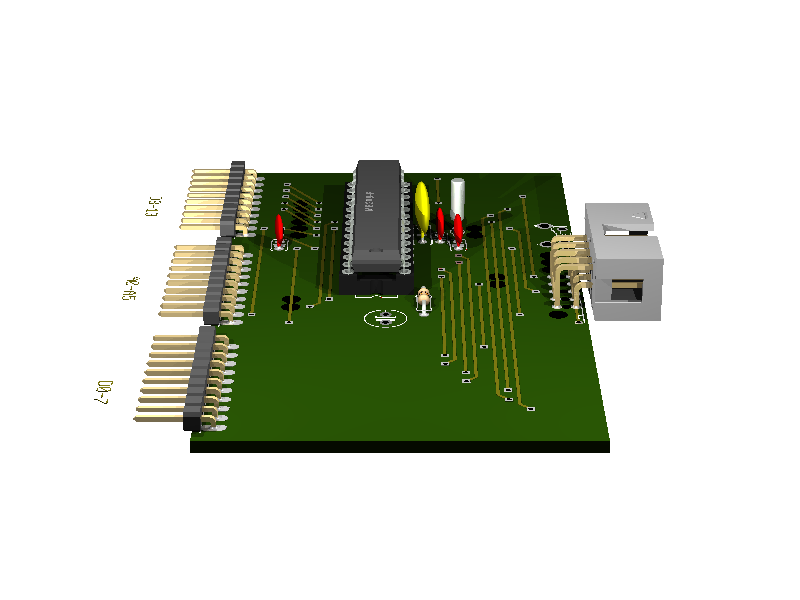
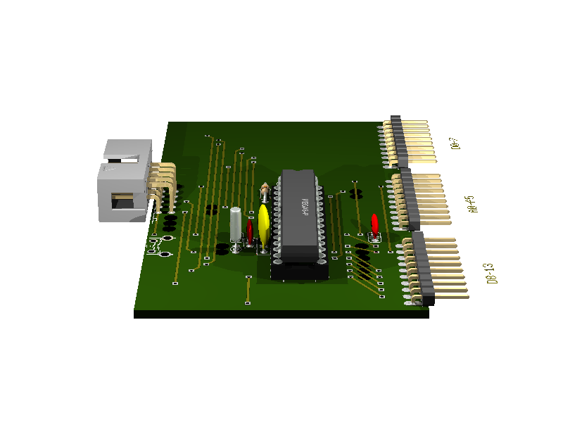
3. Atmega8
Status: OK
Arduino compatible board for Atmega8/48/88/168 and maybe others also.
- features:
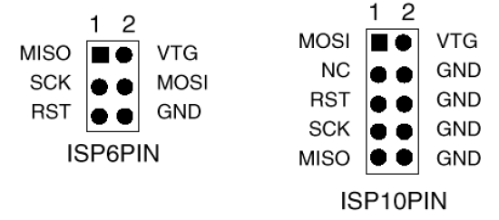
- reset button
- 10 pin ISP connector
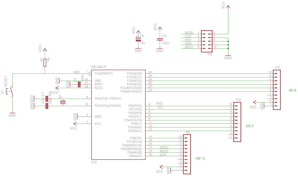
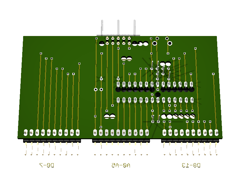
3.1. Pins
| board pin | AVR pin | Arduino pin | comment |
|---|---|---|---|
| 0 | PB0 | D8 | |
| 1 | PB1 | D9 | |
| 2 | PB2 | D10 | |
| 3 | PB3 | D11 | MOSI |
| 4 | PB4 | D12 | MISO |
| 5 | PB5 | D13 | SCK |
| 6 | NC | ||
| 7 | NC | ||
| 8 | POWER | ||
| 9 | GND | ||
| 10 | PC0 | A0 | |
| 11 | PC1 | A1 | |
| 12 | PC2 | A2 | |
| 13 | PC3 | A3 | |
| 14 | PC4 | A4 | |
| 15 | PC5 | A5 | |
| 16 | NC | ||
| 17 | NC | ||
| 18 | POWER | ||
| 19 | GND | ||
| 20 | PD0 | D0 | RxD |
| 21 | PD1 | D1 | TxD |
| 22 | PD2 | D2 | |
| 23 | PD3 | D3 | |
| 24 | PD4 | D4 | |
| 25 | PD5 | D5 | |
| 26 | PD6 | D6 | |
| 27 | PD7 | D7 | |
| 28 | POWER | ||
| 29 | GND |
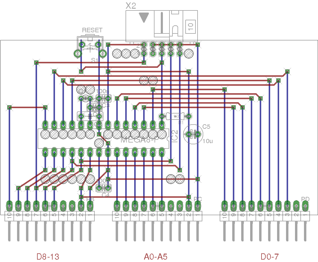
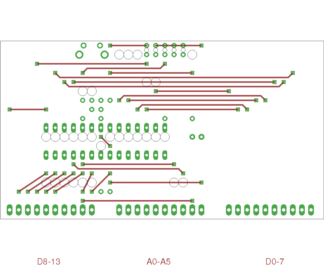
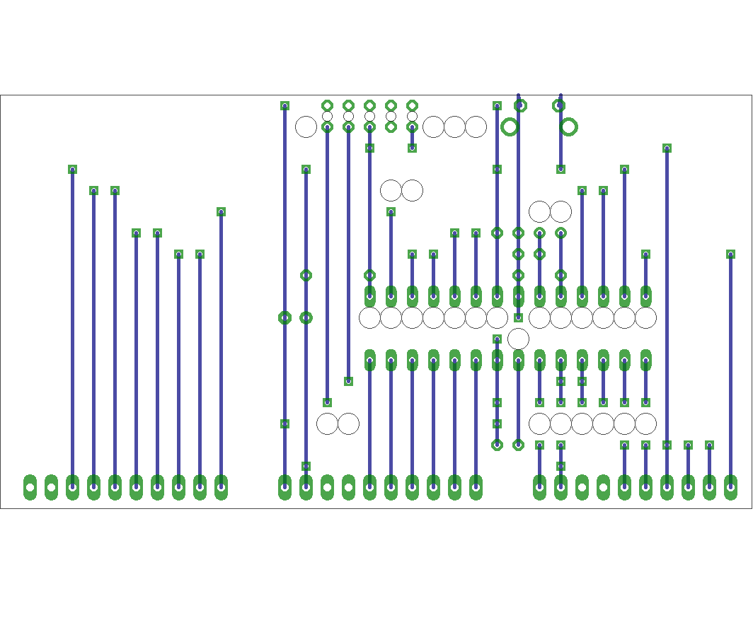
3.2. Schematic
3.4. Partlist
part value position C1 22p (1.05 1.2) C2 22p (1 1.1) C3 100n (1.15 1.3) C4 100n (1.15 0.3) C5 10u (2.15 0.9) IC2 MEGA8-P (1.15 0.85) PB (0.55 0.1) PC (1.75 0.1) PD (2.95 0.1) Q1 (0.95 1.3) R1 10k (1.95 1.1) S1 RESET (1 1.85) X2 (1.8 1.85)